
544 lines
29 KiB
Markdown
544 lines
29 KiB
Markdown
---
|
||
page-title: "How to secure IOT devices with VLANs and firewall rules on an Ubiquiti EdgeRouter-X and a MikroTik switch running SwOS Lite · GeekBitZone.com - Passionate About Tech"
|
||
url: https://www.geekbitzone.com/posts/2021/networking/vlans/vlan-edgerouter-mikrotik/edgerouter-mikrotik-swos-vlan/
|
||
date: "2024-12-16 17:41:48"
|
||
---
|
||
**Deprecation Notice:** *This article was written more than a year ago which means that its information might no longer be up-to-date. We cannot therefore guarantee the accuracy of it's contents.*
|
||
|
||
---
|
||
|
||
## Table of Contents
|
||
|
||
- [Firmware versions used](https://www.geekbitzone.com/posts/2021/networking/vlans/vlan-edgerouter-mikrotik/edgerouter-mikrotik-swos-vlan/#firmware-versions-used)
|
||
- [Network overview](https://www.geekbitzone.com/posts/2021/networking/vlans/vlan-edgerouter-mikrotik/edgerouter-mikrotik-swos-vlan/#network-overview)
|
||
- [Setting up a VLAN on the EdgeRouter](https://www.geekbitzone.com/posts/2021/networking/vlans/vlan-edgerouter-mikrotik/edgerouter-mikrotik-swos-vlan/#setting-up-a-vlan-on-the-edgerouter)
|
||
- [Enabling VLAN on the switch0 interface](https://www.geekbitzone.com/posts/2021/networking/vlans/vlan-edgerouter-mikrotik/edgerouter-mikrotik-swos-vlan/#enabling-vlan-on-the-switch0-interface)
|
||
- [Creating a DHCP server for the VLAN](https://www.geekbitzone.com/posts/2021/networking/vlans/vlan-edgerouter-mikrotik/edgerouter-mikrotik-swos-vlan/#creating-a-dhcp-server-for-the-vlan)
|
||
- [Setting up Firewall NAT Groups on the EdgeRouter](https://www.geekbitzone.com/posts/2021/networking/vlans/vlan-edgerouter-mikrotik/edgerouter-mikrotik-swos-vlan/#setting-up-firewall-nat-groups-on-the-edgerouter)
|
||
- [Setting up Firewall Policies on the EdgeRouter](https://www.geekbitzone.com/posts/2021/networking/vlans/vlan-edgerouter-mikrotik/edgerouter-mikrotik-swos-vlan/#setting-up-firewall-policies-on-the-edgerouter)
|
||
- [Setting up a VLAN on the CSS610-8G-2S+IN](https://www.geekbitzone.com/posts/2021/networking/vlans/vlan-edgerouter-mikrotik/edgerouter-mikrotik-swos-vlan/#setting-up-a-vlan-on-the-css610-8g-2sin)
|
||
- [Verifying the setup](https://www.geekbitzone.com/posts/2021/networking/vlans/vlan-edgerouter-mikrotik/edgerouter-mikrotik-swos-vlan/#verifying-the-setup)
|
||
- [Test 1: Can the IOT device reach the Internet?](https://www.geekbitzone.com/posts/2021/networking/vlans/vlan-edgerouter-mikrotik/edgerouter-mikrotik-swos-vlan/#test-1-can-the-iot-device-reach-the-internet)
|
||
- [Test 2: Can the IOT device reach other devices outside VLAN 10?](https://www.geekbitzone.com/posts/2021/networking/vlans/vlan-edgerouter-mikrotik/edgerouter-mikrotik-swos-vlan/#test-2-can-the-iot-device-reach-other-devices-outside-vlan-10)
|
||
- [Test 3: Can the IOT device reach the router (gateway)?](https://www.geekbitzone.com/posts/2021/networking/vlans/vlan-edgerouter-mikrotik/edgerouter-mikrotik-swos-vlan/#test-3-can-the-iot-device-reach-the-router-gateway)
|
||
- [Test 4: Can devices on the main network (outside VLAN 10) reach the IOT device?](https://www.geekbitzone.com/posts/2021/networking/vlans/vlan-edgerouter-mikrotik/edgerouter-mikrotik-swos-vlan/#test-4-can-devices-on-the-main-network-outside-vlan-10-reach-the-iot-device)
|
||
- [Summary](https://www.geekbitzone.com/posts/2021/networking/vlans/vlan-edgerouter-mikrotik/edgerouter-mikrotik-swos-vlan/#summary)
|
||
- [References](https://www.geekbitzone.com/posts/2021/networking/vlans/vlan-edgerouter-mikrotik/edgerouter-mikrotik-swos-vlan/#references)
|
||
|
||
---
|
||
|
||
## How to secure IOT devices with VLANs and firewall rules on an Ubiquiti EdgeRouter-X and a MikroTik switch running SwOS Lite
|
||
|
||
The Ubiquiti Networks™ EdgeMAX® [EdgeRouter™ X](https://www.ui.com/edgemax/edgerouter-x/) and the MikroTik [CSS610-8G-2S+IN](https://mikrotik.com/product/css610_8g_2s_in) layer 2 switch are very affordable networking devices sold by respective vendors in this price bracket. We will in this tutorial explore how to set up a Virtual Local Area Network (**VLAN**) with firewall rules between an EdgeRouter™ X and a CSS610-8G-2S+IN switch running [SwOS Lite](https://wiki.mikrotik.com/wiki/SwOS/CSS610).
|
||
|
||
---
|
||
|
||
## Firmware versions used
|
||
|
||
The following firmware versions were used in this article:
|
||
|
||
- [EdgeOS v2.0.9-hotfix.1](https://www.ui.com/download/edgemax/default/default/edgerouter-er-xer-x-sfpep-r6er-10x-firmware-v209-hotfix1)
|
||
- [SwOS Lite 2.13](https://www.mikrotik.com/download)
|
||
|
||
---
|
||
|
||
## Network overview
|
||
|
||
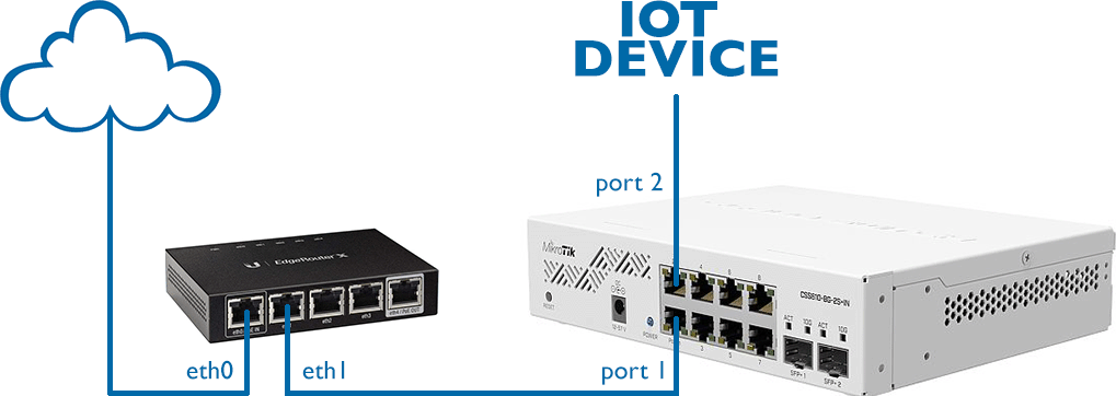
In this simple network diagram we have assumed that the Internet (WAN) is connected to port **eth0** on the EdgeRouter. On the LAN side, **eth1** is connected to **port 1** on the MikroTik switch. Finally, on **port 2**, we have connected an insecure Internet of Things (IOT) device which we will isolate into its own VLAN.
|
||
|
||
|
||
|
||
---
|
||
|
||
## Setting up a VLAN on the EdgeRouter
|
||
|
||
We will begin by logging in to the EdgeRouter. Open your router’s admin page, which in our case is `192.168.1.1`, and type in your `username` and `password`.
|
||
|
||
|
||
|
||
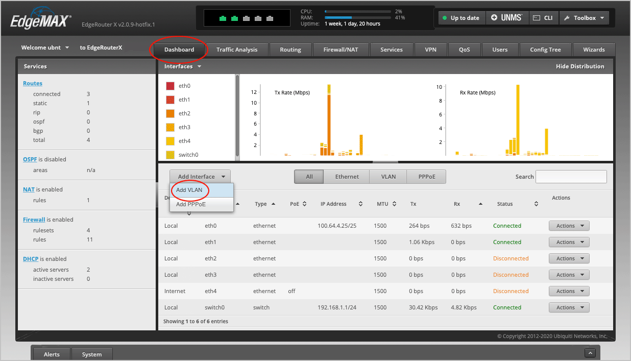
On the main **Dashboard**, select **Add Interface > Add VLAN**.
|
||
|
||
|
||
|
||
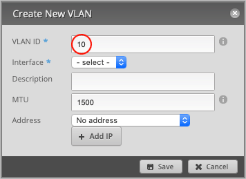
Pick a **VLAN ID** number between 0-4094. We have chosen `10`.
|
||
|
||
|
||
|
||
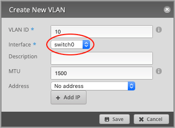
Set **Interface** to `switch0`.
|
||
|
||
|
||
|
||
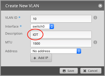
Type in a **Description** for this VLAN (optional). We will name it `IOT`.
|
||
|
||
|
||
|
||
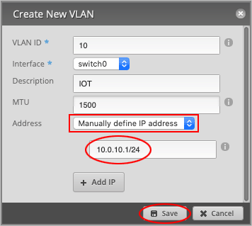
Set **Address** to `Manually define IP address`. We have chosen: `10.0.10.1/24`, but feel free to use any IP within the reserved [RFC1918](https://tools.ietf.org/html/rfc1918) ranges.
|
||
|
||
Press **Save** to close the window.
|
||
|
||
|
||
|
||
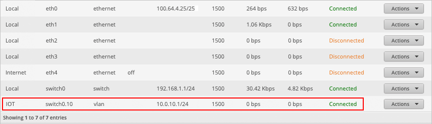
We can now see on the main dashboard that a new interface, **switch0.10**, has been created. This is the interface for our IOT VLAN 10.
|
||
|
||
|
||
|
||
---
|
||
|
||
## Enabling VLAN on the switch0 interface
|
||
|
||
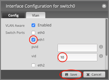
We will now make the **switch0** interface VLAN-aware by tagging VLAN ID **10** to port **eth1**.
|
||
|
||
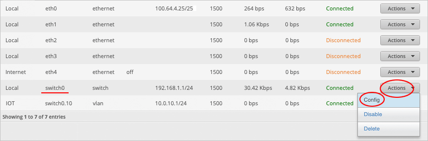
Place your mouse cursor over the **switch0** row and select **Actions > Config**.
|
||
|
||
*Note: do not accidentally select the IOT switch0.10 interface!*
|
||
|
||
|
||
|
||
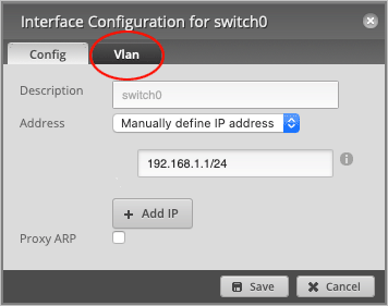
Navigate to the **Vlan** tab.
|
||
|
||
|
||
|
||
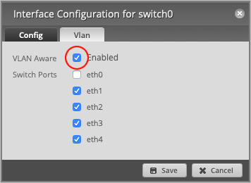
`Enable` the **VLAN Aware** checkbox.
|
||
|
||
|
||
|
||
Make sure that **Switch Ports** have been `enabled` on **eth1** and set **vid** to VLAN `10`.
|
||
|
||
|
||
|
||
Press **Save** to close the window.
|
||
|
||
*Note: The **vid** value is for tagged traffic leaving the port, while **pvid** is used for untagged traffic arriving at the port.*
|
||
|
||
---
|
||
|
||
## Creating a DHCP server for the VLAN
|
||
|
||
We will now create a DHCP Server so that any devices connected to this VLAN will automatically receive an IP address.
|
||
|
||
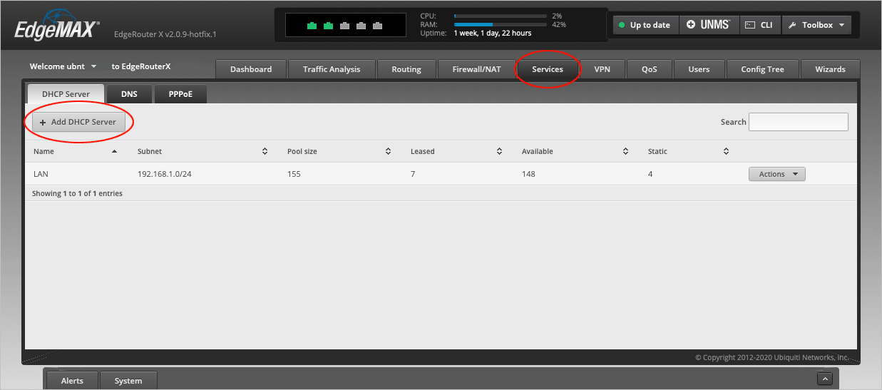
Navigate to the **Services > DHCP Server** tab and select **Add DHCP Server**.
|
||
|
||
|
||
|
||
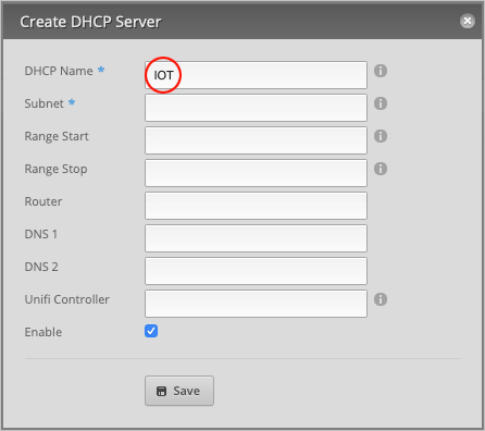
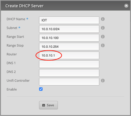
Give the server a **DHCP Name**. We will call it `IOT`.
|
||
|
||
|
||
|
||
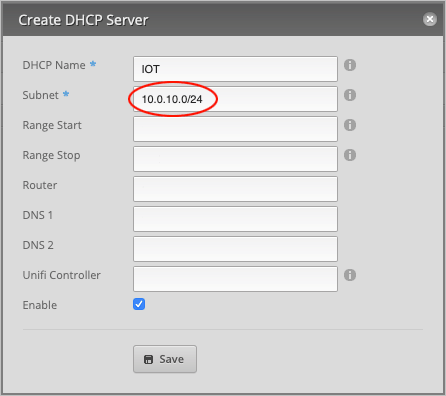
For the **Subnet**, type `10.0.10.0/24`.
|
||
|
||
|
||
|
||
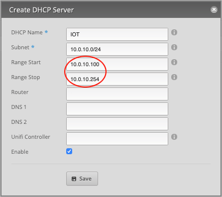
Our DHCP **Range Start** is `10.0.10.100` and **Range Stop** will be `10.0.10.254`. Feel free to use any range, but bear in mind that if you want to assign static IP addresses to your devices, this entire IP range cannot be occupied by DHCP.
|
||
|
||
|
||
|
||
Set the **Router** address to `10.0.10.1`.
|
||
|
||
|
||
|
||
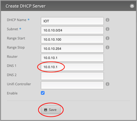
Finally, assign a **DNS 1** record to this DHCP server. We will simply use the *router’s* address, `10.0.10.1`, since all traffic will flow through here anyway. (Optionally, assign a second DNS record, such as `1.1.1.1` or `8.8.8.8`, under **DNS 2** for added redundancy.)
|
||
|
||
|
||
|
||
Press **Save** to close the window.
|
||
|
||
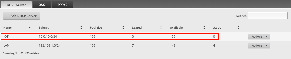
If we look at the page we can now see that **IOT** has been added to the list of DHCP servers.
|
||
|
||
|
||
|
||
---
|
||
|
||
## Setting up Firewall NAT Groups on the EdgeRouter
|
||
|
||
We will now set up a few firewall rules to prevent IOT devices from communicating with other devices on the local area network and to only allow them Internet access.
|
||
|
||
*Note: This section has deliberately been made as simple as possible and does not cover every possible firewall rule since every user’s network setup is different.*
|
||
|
||
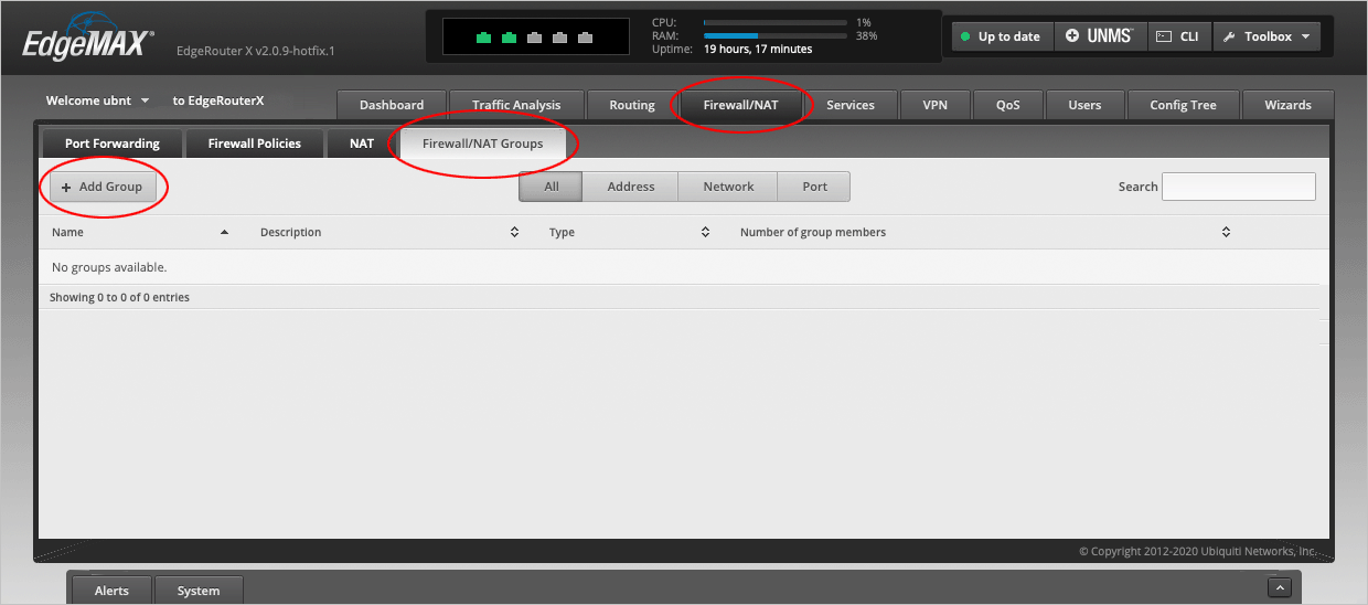
Navigate to the **Firewall/NAT > Firewall/NAT Groups** tab and select **Add Group**.
|
||
|
||
|
||
|
||
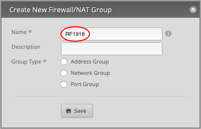
We will now define a **Network Group** of *Private Internets* based on the [RFC1918](https://tools.ietf.org/html/rfc1918) standard, which we will later use in our firewall rules.
|
||
|
||
Under **Name**, type `RFC1918`.
|
||
|
||
|
||
|
||
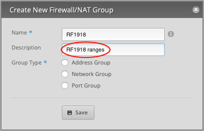
Give a **Description** (optional). We will type `RFC1918 ranges`.
|
||
|
||
|
||
|
||
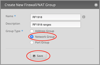
Set **Group Type** to `Network Group` and press **Save** to close the window.
|
||
|
||
|
||
|
||
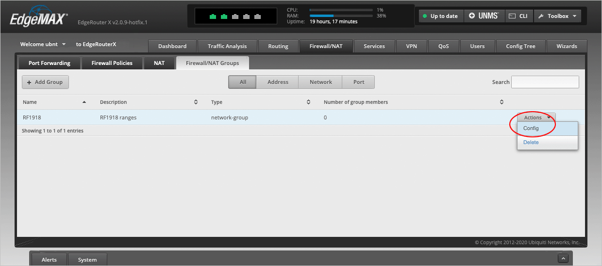
We will now edit our newly created network group. On the **RFC1918** line, select **Actions > Config**.
|
||
|
||
|
||
|
||
Under **Network**, type the following three RFC1918 ranges:
|
||
|
||
- 10.0.0.0/8
|
||
- 172.16.0.0/12
|
||
- 192.168.0.0/16
|
||
|
||
Press **Add New** to create another entry and **Save** to confirm the changes.
|
||
|
||
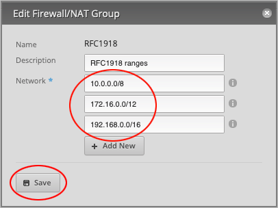
|
||
|
||
This window will not close until you press **X** in the upper right corner.
|
||
|
||
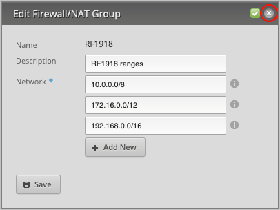
|
||
|
||
Confirm that the **Number of group members** column shows **3** members.
|
||
|
||

|
||
|
||
---
|
||
|
||
## Setting up Firewall Policies on the EdgeRouter
|
||
|
||
With the Network Group set up out of the way, we will now set up firewall policies. Our plan is to block access to the local area network as well as the router from the IOT network and only allow direct Internet access. Safe devices, *outside* the IOT network, should still be able to communicate with the IOT devices, but not the other way around.
|
||
|
||
The EdgeRouter defines traffic as such:
|
||
|
||
- **IN** - Traffic coming from the VLAN into the EdgeRouter.
|
||
- **OUT** - Traffic going out of the EdgeRouter and into the VLAN.
|
||
- **LOCAL** - Traffic on the VLAN itself (broadcasts and inter-vlan communication).
|
||
|
||
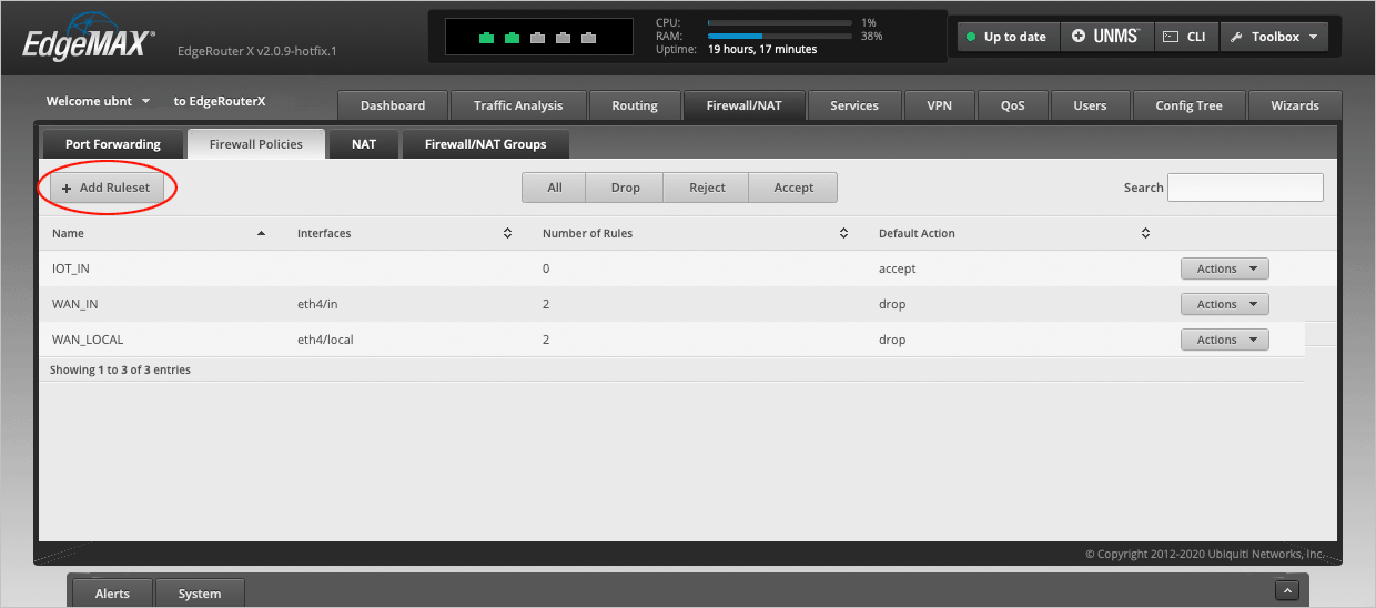
Navigate to the **Firewall/NAT > Firewall Policies** tab and select **Add Ruleset**.
|
||
|
||
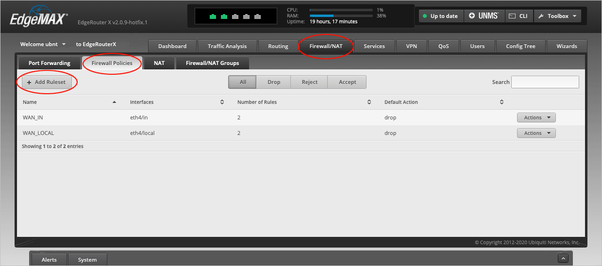
|
||
|
||
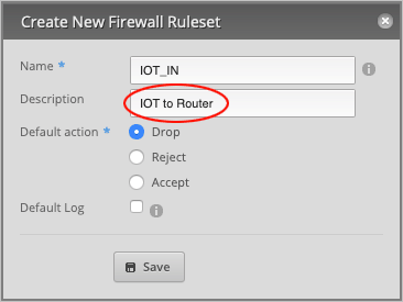
In the **Create New Firewall Ruleset** window, type `IOT_IN` in the **Name** field.
|
||
|
||
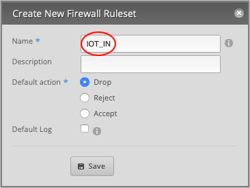
|
||
|
||
Type a **Description** (optional) for this rule. Will type `IOT to Router`.
|
||
|
||
|
||
|
||
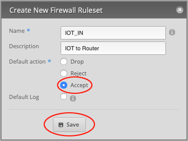
Finally, set the **Default action** to `Accept` and press **Save** to close the window.
|
||
|
||
|
||
|
||
We will now repeat the previous step by creating another rule, which this time is a *local* rule.
|
||
|
||
Press the **Add Ruleset** button.
|
||
|
||
|
||
|
||
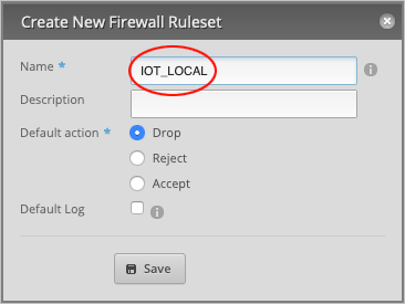
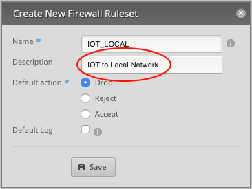
In the **Name** field, type `IOT_LOCAL`.
|
||
|
||
|
||
|
||
Type in a **Description** (optional) for this rule. We will call it `IOT to Local Network`.
|
||
|
||
|
||
|
||
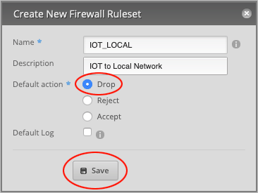
Make sure that the **Default action** is set to `Drop` and press **Save** to close the window.
|
||
|
||
|
||
|
||
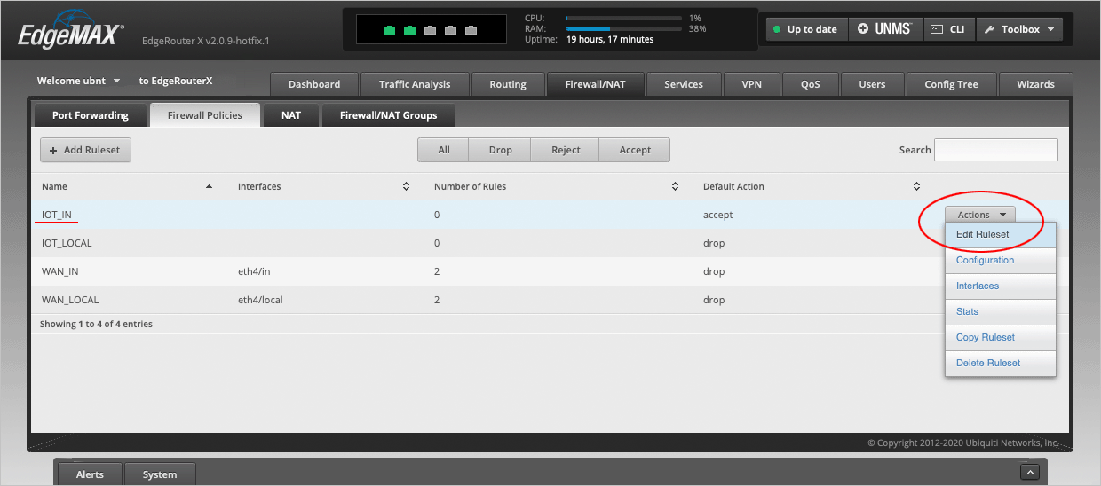
We will now edit the **IOT\_IN** Ruleset. Place your cursor over this line and select **Actions > Edit Ruleset**.
|
||
|
||
|
||
|
||
On the **Ruleset Configuration for IOT\_IN** page, select **Add New Rule**.
|
||
|
||

|
||
|
||
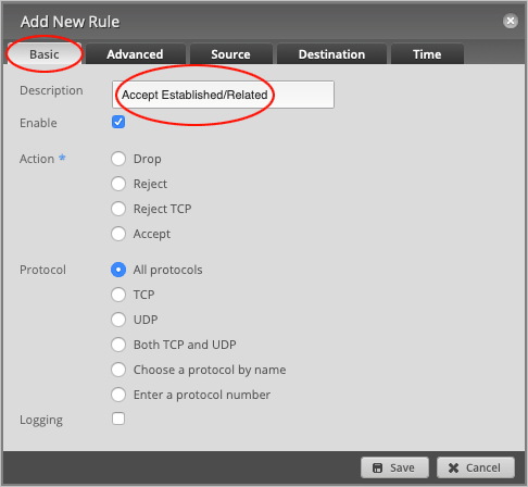
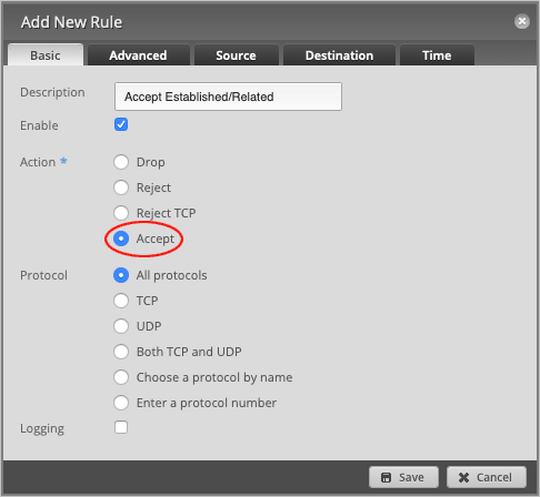
On the **Basic** tab, type in a **Description** for this rule. We will write `Accept Established/Related`.
|
||
|
||
|
||
|
||
Change the default **Action** to `Accept`.
|
||
|
||
|
||
|
||
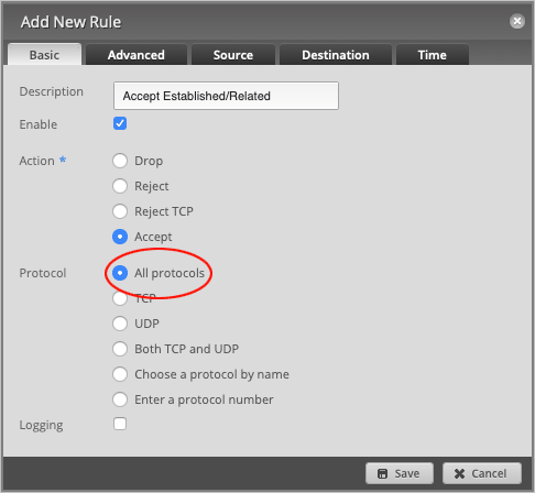
Leave **Protocol** set to `All protocols`.
|
||
|
||
|
||
|
||
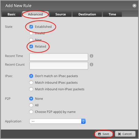
Head over to the **Advanced** tab and set **State** to `Established` and `Related`.
|
||
|
||
Press **Save** to close the window.
|
||
|
||
|
||
|
||
On the **Ruleset Configuration for IOT\_IN** page, press the **Add New Rule** button to create another rule.
|
||
|
||

|
||
|
||
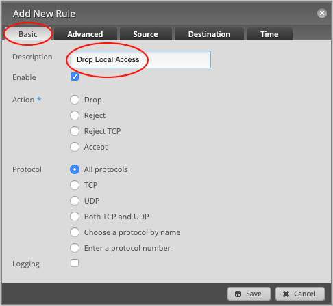
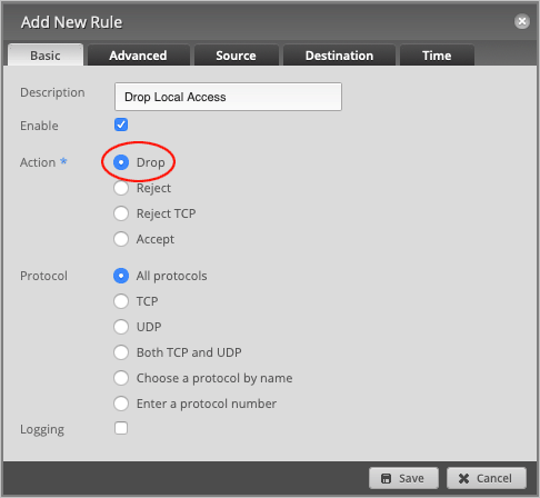
On the **Basic** tab, change the **Description** to `Drop Local Access`.
|
||
|
||
|
||
|
||
Set default **Action** to `Drop`.
|
||
|
||
|
||
|
||
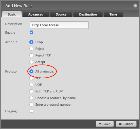
Leave **Protocol** set to `All protocols`.
|
||
|
||
|
||
|
||
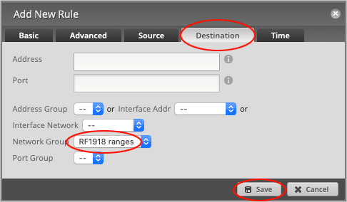
Head over to the **Destination** tab and set the **Network Group** to `RF1918 ranges`.
|
||
|
||
Press **Save** to close the window.
|
||
|
||
|
||
|
||
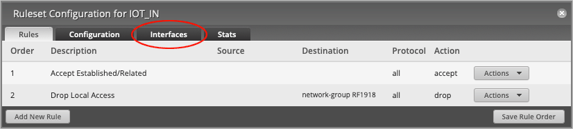
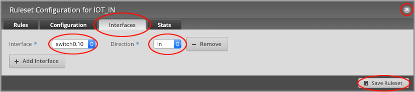
On the **Ruleset Configuration for IOT\_IN** page, head over to the **Interfaces** tab.
|
||
|
||
|
||
|
||
On the **Interfaces** tab, set **Interface** to `switch0.10` and change the **Direction** to `in`.
|
||
|
||
Press **Save Ruleset**, followed by the **X** button to close the window.
|
||
|
||
|
||
|
||
We will now open up two ports for *DNS* and *DHCP* requests.
|
||
|
||
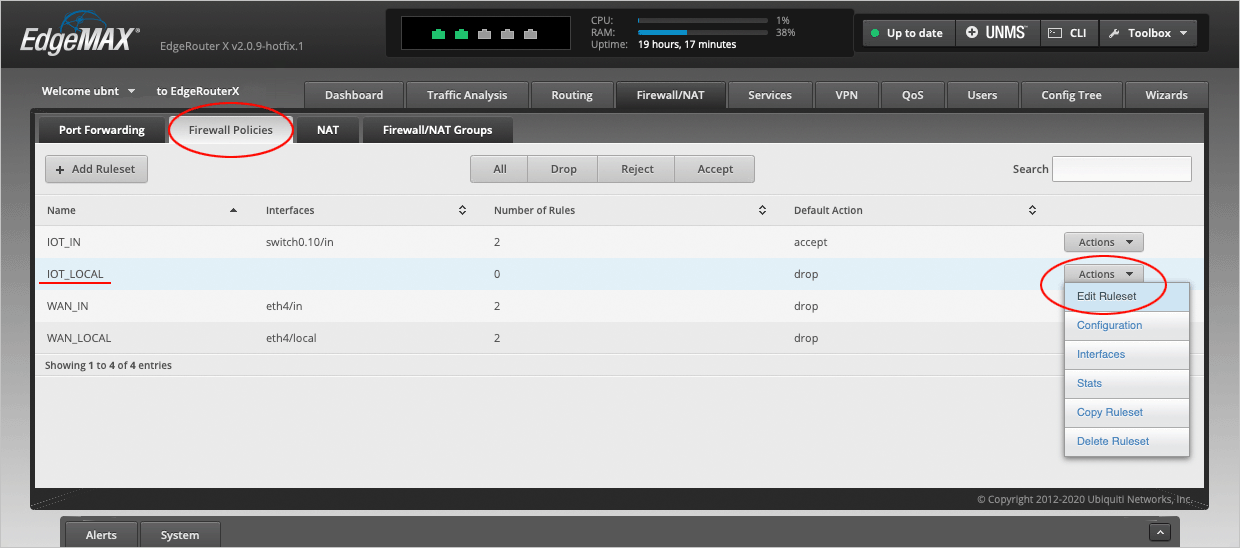
On the **Firewall Policies** page, place your cursor over the **IOT\_LOCAL** row and select **Actions > Edit Ruleset**.
|
||
|
||
|
||
|
||
On the **Ruleset Configuration for IOT\_LOCAL** page, press **Add New Rule**.
|
||
|
||

|
||
|
||
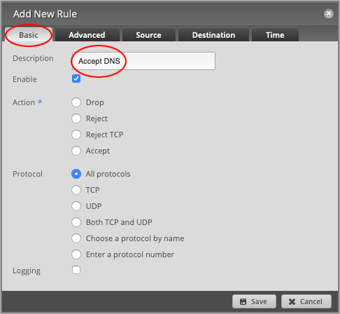
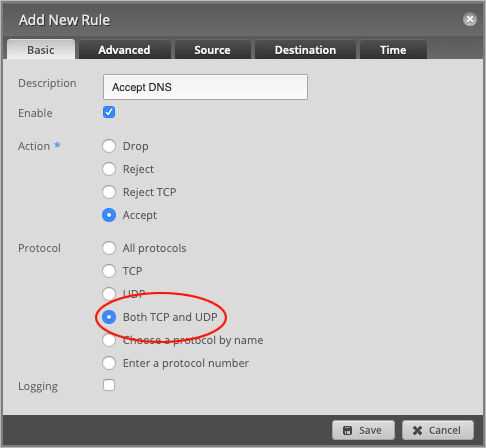
On the **Basic** tab, change the **Description** to `Accept DNS`.
|
||
|
||
|
||
|
||
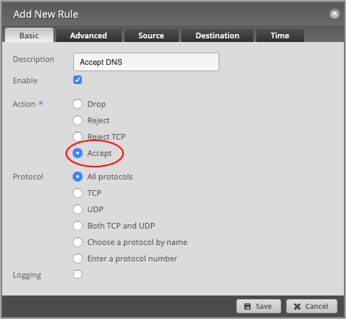
Set the default **Action** to `Accept`.
|
||
|
||
|
||
|
||
Set the **Protocol** to `Both TCP and UDP`.
|
||
|
||
|
||
|
||
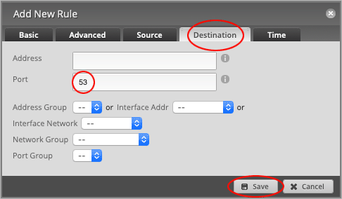
Head over to the **Destination** tab and set the **Port** number to `53`.
|
||
|
||
Press **Save** to close the window.
|
||
|
||
|
||
|
||
Back on the **Ruleset Configuration for IOT\_LOCAL** page, press the **Add New Rule** button.
|
||
|
||

|
||
|
||
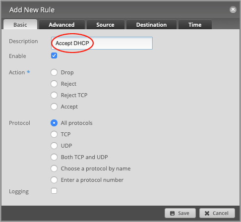
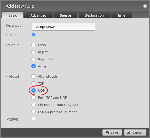
Change the **Description** to `Accept DHCP`.
|
||
|
||
|
||
|
||
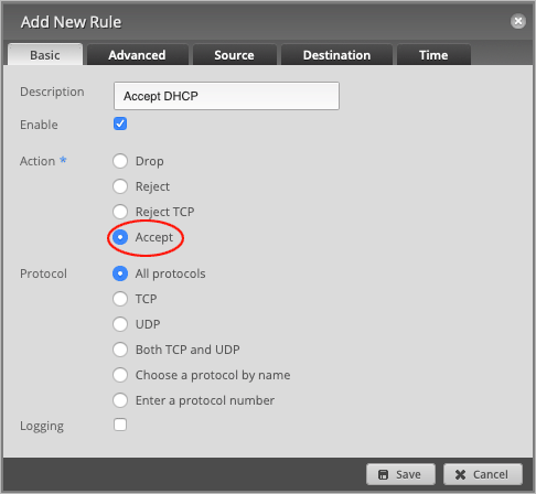
Set the default **Action** to `Accept`.
|
||
|
||
|
||
|
||
Set the **Protocol** to `UDP`.
|
||
|
||
|
||
|
||
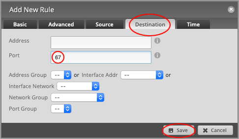
Head over to the **Destination** tab and set the **Port** number to `67`.
|
||
|
||
Press **Save** to close the window.
|
||
|
||
|
||
|
||
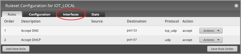
On the **Ruleset Configuration for IOT\_LOCAL** page, head over to the **Interfaces** tab.
|
||
|
||
|
||
|
||
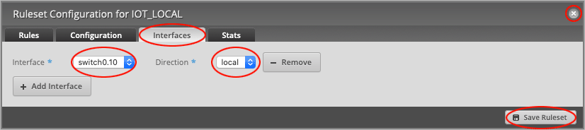
On the **Interfaces** tab, set **Interface** to `switch0.10` and change the **Direction** to `local`.
|
||
|
||
Press **Save Ruleset**, followed by the **X** button to close the window.
|
||
|
||
|
||
|
||
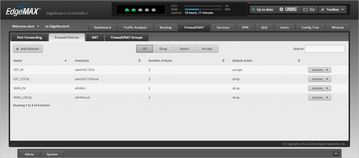
The completed Firewall Policies page should now look like this.
|
||
|
||
|
||
|
||
We have now finished configuring the EdgeRouter and will head over to the MikroTik switch to set up a VLAN.
|
||
|
||
---
|
||
|
||
## Setting up a VLAN on the CSS610-8G-2S+IN
|
||
|
||
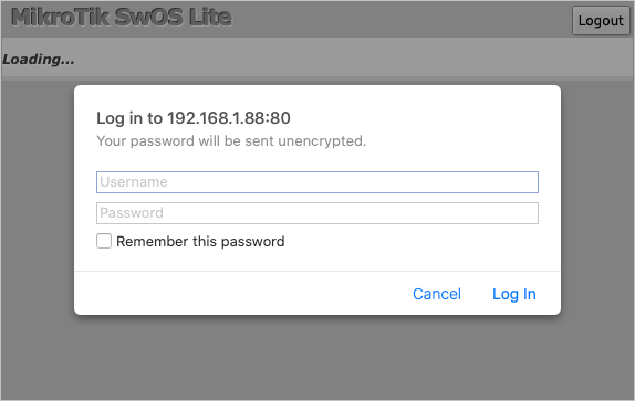
We will begin by logging in to the CSS610-8G-2S+IN switch. Open the admin page, which in our case is `192.168.1.88`, and type in your `username` and `password`.
|
||
|
||
|
||
|
||
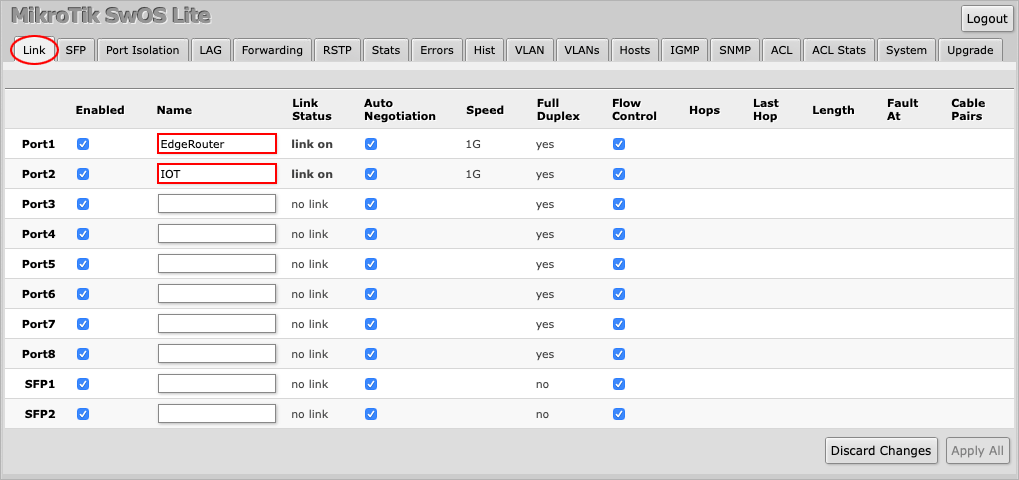
We can see on the **Link** tab that **Port1** is connected to the `EdgeRouter` and that **Port2** is connected to the `IOT` device. (We have named the ports ourselves).
|
||
|
||
|
||
|
||
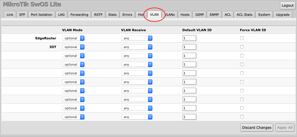
With this knowledge at hand, navigate to the **VLAN** tab.
|
||
|
||
|
||
|
||
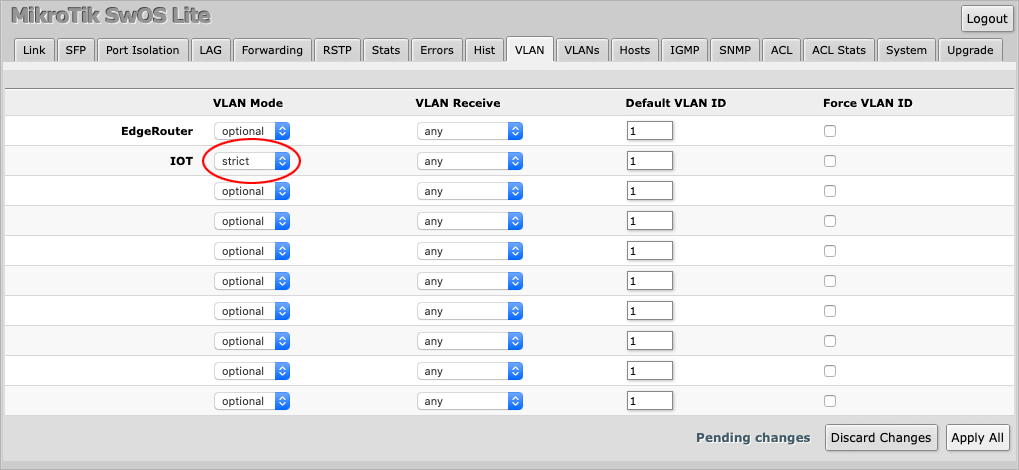
On the **IOT** port, set **VLAN Mode** to `strict`.
|
||
|
||
|
||
|
||
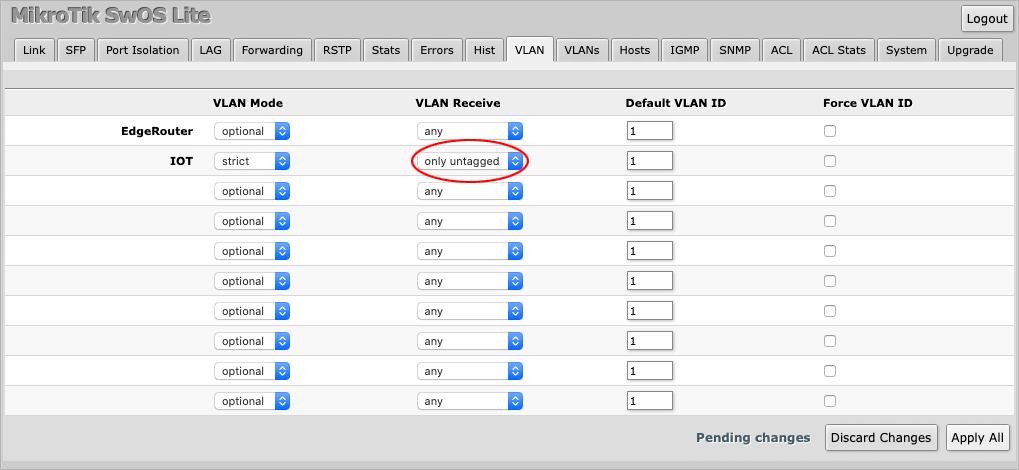
Set **VLAN Receive** to accept `only untagged` traffic.
|
||
|
||
|
||
|
||
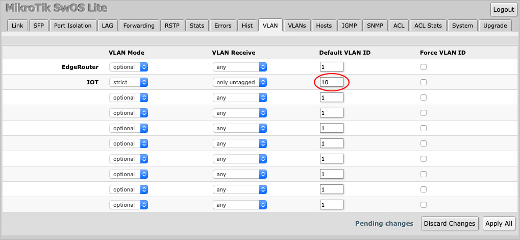
Finally, set the **Default VLAN ID** to `10`, which is the VLAN value used on the EdgeRouter.
|
||
|
||
|
||
|
||
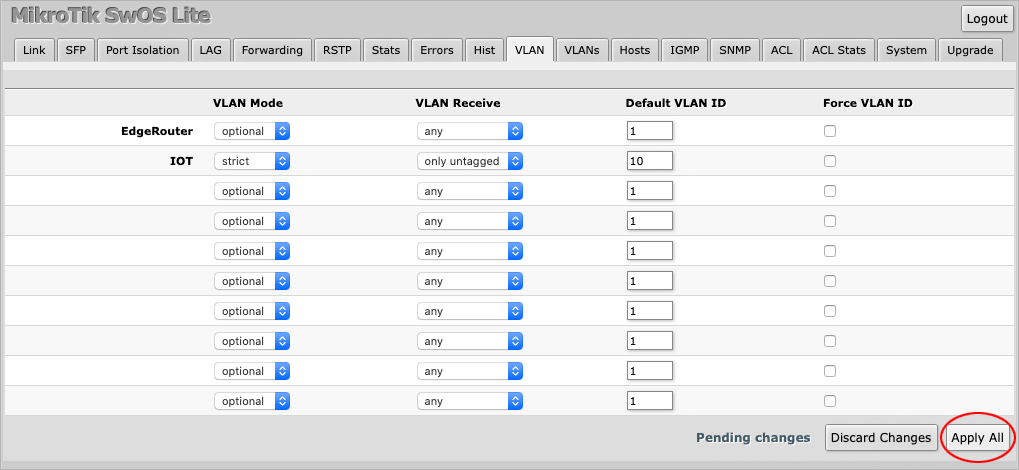
Press **Apply All** to save the changes.
|
||
|
||
|
||
|
||
Next, navigate to the **VLANs** tab where you will be presented by a blank page.
|
||
|
||

|
||
|
||
Press the **Append** button to create a new entry.
|
||
|
||

|
||
|
||
Enter `10` under **VLAN ID**.
|
||
|
||

|
||
|
||
Only check the port **Members** that should belong to VLAN 10. In this case `one` and `two` have been checked, i.e. the EdgeRouter and the IOT Device.
|
||
|
||

|
||
|
||
Press **Apply All** to save the changes.
|
||
|
||

|
||
|
||
The VLAN has now been set up on the MikroTik switch.
|
||
|
||
---
|
||
|
||
## Verifying the setup
|
||
|
||
We are now ready to test if the VLAN and the firewall rules actually work. In the following section we will be logging in to our devices, both inside and outside the IOT VLAN to see if certain destinations can reached with the `ping` command.
|
||
|
||
- Our EdgeRouter has an IP address of `192.168.1.1` on the main network and `10.0.10.1` on the IOT VLAN.
|
||
- The IOT Device has an IP address of `10.0.10.100`.
|
||
- We also have a computer on the main network with an IP address of `192.168.1.100`.
|
||
|
||
---
|
||
|
||
### Test 1: Can the IOT device reach the Internet?
|
||
|
||
We will ping `google.com` from `10.0.10.100` (inside VLAN 10).
|
||
|
||
```
|
||
$ ping google.com
|
||
|
||
PING google.com (172.217.169.78): 56 data bytes
|
||
64 bytes from 172.217.169.78: icmp_seq=0 ttl=118 time=1.547 ms
|
||
64 bytes from 172.217.169.78: icmp_seq=1 ttl=118 time=1.590 ms
|
||
64 bytes from 172.217.169.78: icmp_seq=2 ttl=118 time=1.713 ms
|
||
--- google.com ping statistics ---
|
||
3 packets transmitted, 3 packets received, 0.0% packet loss
|
||
round-trip min/avg/max/stddev = 1.547/1.617/1.713/0.070 ms
|
||
```
|
||
|
||
**Result:** The IOT device *can* reach the internet.
|
||
|
||
---
|
||
|
||
### Test 2: Can the IOT device reach other devices outside VLAN 10?
|
||
|
||
We will ping `192.168.1.100`, which is a computer on the main network, from `10.0.10.100`.
|
||
|
||
```
|
||
$ ping 192.168.1.100
|
||
|
||
PING 192.168.1.100 (192.168.1.100): 56 data bytes
|
||
Request timeout for icmp_seq 0
|
||
Request timeout for icmp_seq 1
|
||
Request timeout for icmp_seq 2
|
||
--- 192.168.1.100 ping statistics ---
|
||
4 packets transmitted, 0 packets received, 100.0% packet loss
|
||
```
|
||
|
||
**Result:** The IOT device *can not* reach devices outside VLAN 10 on a private network.
|
||
|
||
---
|
||
|
||
### Test 3: Can the IOT device reach the router (gateway)?
|
||
|
||
We will ping `10.0.10.1` and `192.168.1.1` from `10.0.10.100`.
|
||
|
||
```
|
||
$ ping 10.0.10.1
|
||
|
||
PING 10.0.10.1 (10.0.10.1): 56 data bytes
|
||
Request timeout for icmp_seq 0
|
||
Request timeout for icmp_seq 1
|
||
Request timeout for icmp_seq 2
|
||
--- 10.0.10.1 ping statistics ---
|
||
4 packets transmitted, 0 packets received, 100.0% packet loss
|
||
|
||
$ ping 192.168.1.1
|
||
|
||
PING 192.168.1.1 (192.168.1.1): 56 data bytes
|
||
Request timeout for icmp_seq 0
|
||
Request timeout for icmp_seq 1
|
||
Request timeout for icmp_seq 2
|
||
--- 192.168.1.1 ping statistics ---
|
||
4 packets transmitted, 0 packets received, 100.0% packet loss
|
||
```
|
||
|
||
**Result:** The router *can not* be reached from within or outside VLAN 10.
|
||
|
||
---
|
||
|
||
### Test 4: Can devices on the main network (outside VLAN 10) reach the IOT device?
|
||
|
||
We will use a computer on the main network, `192.168.1.100`, to ping the IOT device at `10.0.10.100`.
|
||
|
||
```
|
||
$ ping 10.0.10.100
|
||
|
||
PING 10.0.10.100 (10.0.10.100): 56 data bytes
|
||
64 bytes from 10.0.10.100: icmp_seq=0 ttl=63 time=0.870 ms
|
||
64 bytes from 10.0.10.100: icmp_seq=1 ttl=63 time=1.088 ms
|
||
64 bytes from 10.0.10.100: icmp_seq=2 ttl=63 time=1.290 ms
|
||
--- 10.0.10.100 ping statistics ---
|
||
3 packets transmitted, 3 packets received, 0.0% packet loss
|
||
round-trip min/avg/max/stddev = 0.870/1.083/1.290/0.172 ms
|
||
```
|
||
|
||
**Result:** Devices on the main network *can* reach the IOT network.
|
||
|
||
---
|
||
|
||
## Summary
|
||
|
||
This tutorial has shown how you can secure IOT devices from the main network by setting up a Virtual Local Area Network (**VLAN**) with firewall rules between an Ubiquiti Networks™ EdgeMAX® **EdgeRouter™ X**, and a MikroTik **CSS610-8G-2S+IN** switch running **SwOS Lite**.
|
||
|
||
---
|
||
|
||
## References
|
||
|
||
**EdgeRouter™ X**
|
||
[https://www.ui.com/edgemax/edgerouter-x/](https://www.ui.com/edgemax/edgerouter-x/)
|
||
|
||
**CSS610-8G-2S+IN**
|
||
[https://mikrotik.com/product/css610\_8g\_2s\_in](https://mikrotik.com/product/css610_8g_2s_in)
|
||
|
||
**SwOS Lite Manual**
|
||
[https://wiki.mikrotik.com/wiki/SwOS/CSS610](https://wiki.mikrotik.com/wiki/SwOS/CSS610)
|
||
|
||
**EdgeOS v2.0.9-hotfix.1 firmware**
|
||
[https://www.ui.com/download/edgemax/default/default/edgerouter-er-xer-x-sfpep-r6er-10x-firmware-v209-hotfix1](https://www.ui.com/download/edgemax/default/default/edgerouter-er-xer-x-sfpep-r6er-10x-firmware-v209-hotfix1)
|
||
|
||
**SwOS Lite 2.13**
|
||
[https://www.mikrotik.com/download](https://www.mikrotik.com/download)
|
||
|
||
**RFC1918 Private Internets**
|
||
[https://tools.ietf.org/html/rfc1918](https://tools.ietf.org/html/rfc1918) |